Microcontrollers 2
Week 1 — Review of Microcontrollers 1
DE6417 · S1 2026
Today's Agenda
Part 1 (~60 min)
- Embedded Systems & Microcontrollers
- The Arduino Platform & ATmega328P
- C++ Essentials Review
- GPIO & Digital I/O
Part 2 (~60 min)
- Analog to Digital Conversion (ADC)
- Timing & Finite State Machines
- What's Coming in Micro 2
- C++ Practice Session (separate)
Your Micro 1 Journey
From theory to hardware — everything you learned last semester:
Embedded Systems
& Processor Design
C++ Programming
& Data Structures
Arduino Uno
& GPIO Basics
Timing &
State Machines
ADC
Joystick Game
Project
Embedded Systems & Microcontrollers
The foundations of everything we build
What is an Embedded System?
- A dedicated computer designed to perform a specific task
- Operates within a larger system — often invisible to the user
- Optimized for reliability, efficiency, and real-time operation
- Examples: washing machine controller, car ECU, medical devices, traffic lights
Key idea: Unlike general-purpose computers, embedded systems do one thing well.
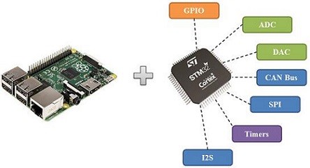
Comparing System Types
| Feature | General Purpose PC | Complex Embedded | Simple Embedded |
|---|---|---|---|
| OS | Windows / macOS | Linux / RTOS | None (bare-metal) |
| CPU | Multi-core GHz | ARM Cortex-A | 8-bit MCU |
| RAM | 8–64 GB | 256 MB–4 GB | 2–32 KB |
| Example | Desktop / Laptop | Smartphone / Router | Arduino / Thermostat |
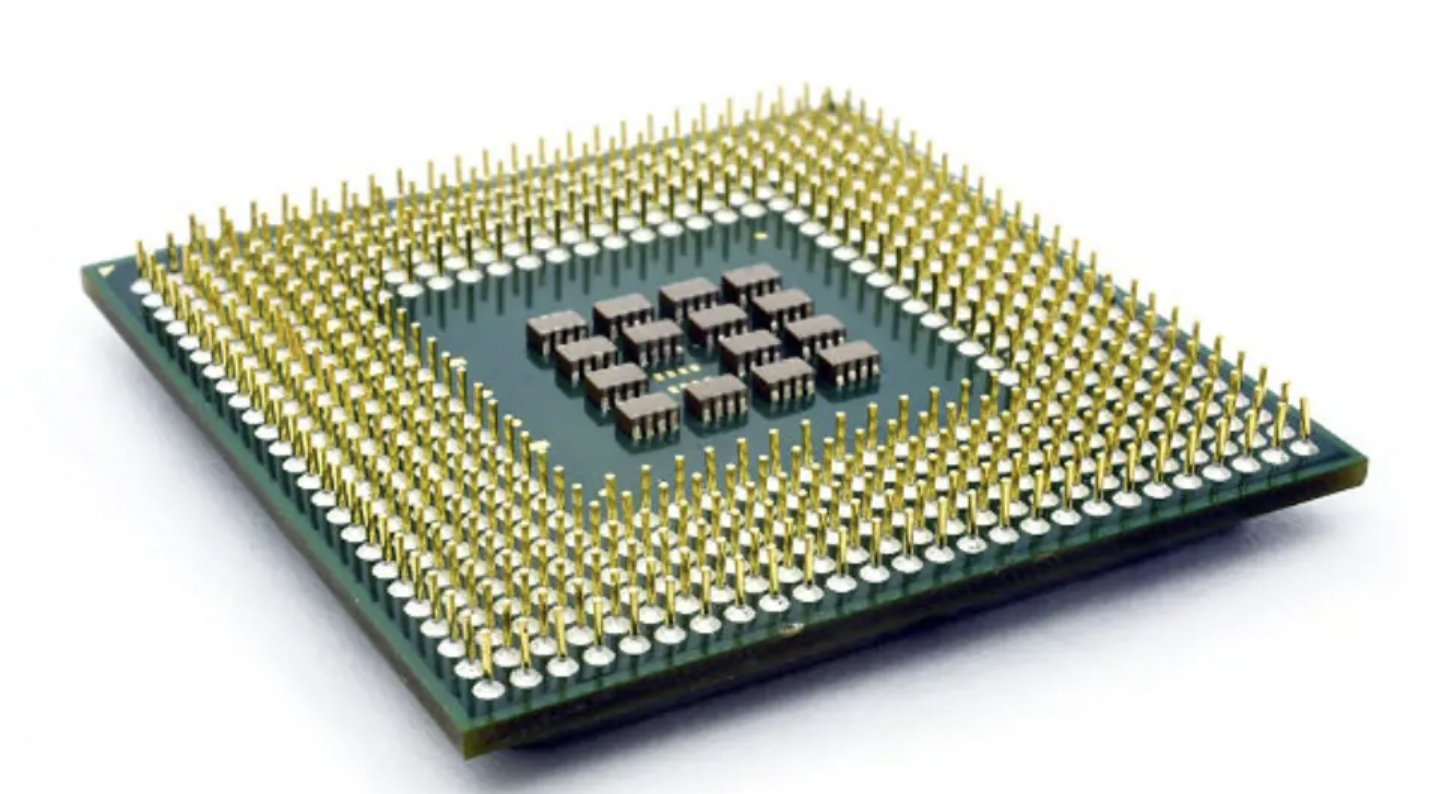
Microprocessor vs Microcontroller
| Feature | Microprocessor | Microcontroller |
|---|---|---|
| Architecture | CPU only | CPU + RAM + ROM + I/O |
| External Components | Many required | Self-contained |
| Power Consumption | High | Low |
| Cost | Expensive | Cheap ($1–$10) |
| Use Case | Laptops, Servers | Sensors, IoT, Robots |
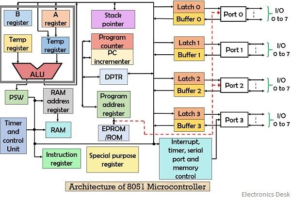
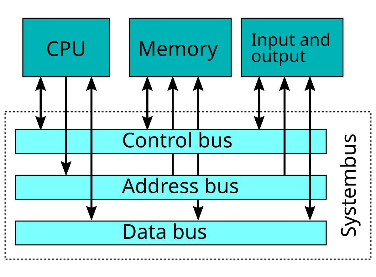
Inside a Microcontroller
All of these are integrated on a single chip:
- CPU — Executes instructions (ALU + Control Unit + Registers)
- Flash (ROM) — Stores your program (non-volatile)
- SRAM — Working memory for variables (volatile)
- GPIO — General Purpose Input/Output pins
- Timers/Counters — Precise timing and counting events
- ADC — Analog to Digital Converter
- Communication — UART, SPI, I2C interfaces
The Arduino Platform
Hardware, software, and the ATmega328P
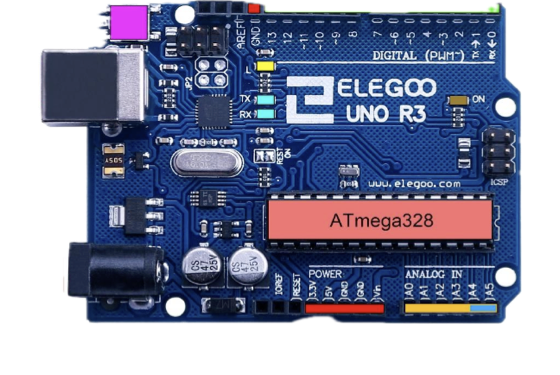
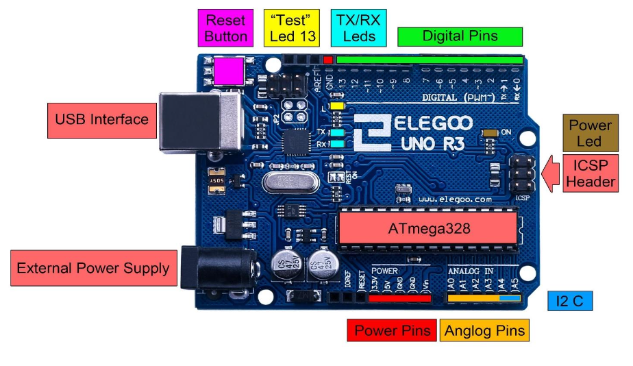
Arduino Uno R3
- MCU: ATmega328P (8-bit AVR, 16 MHz)
- Flash (32 KB): Non-volatile program memory — your compiled sketch is stored here. Retains data when power is off. 0.5 KB is reserved for the bootloader.
- SRAM (2 KB): Static Random-Access Memory — holds variables, the stack, and the heap while your program runs. Volatile — all data is lost when power is removed.
- EEPROM (1 KB): Electrically Erasable Programmable ROM — used to store small amounts of data that must survive power cycles (e.g., calibration values, settings). Limited write cycles (~100,000).
- Digital I/O: 14 pins (6 PWM capable)
- Analog Input: 6 pins (A0–A5, 10-bit ADC)
- Operating Voltage: 5V
The Arduino ecosystem: Hardware + IDE + API/Libraries
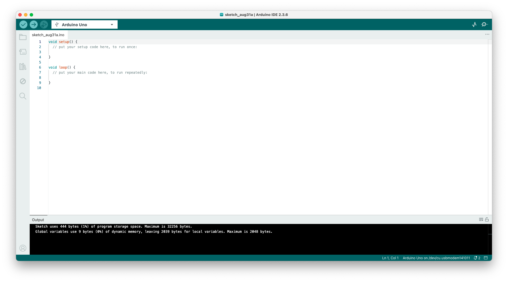
Arduino IDE & Workflow
- Write your sketch (program) in the editor
- Verify (✓) — compiles your code, checks for errors
- Upload (→) — sends compiled code to the board via USB
- Serial Monitor — view data sent from the board
Workflow: Write → Verify → Upload → Test → Repeat
Remember: Arduino sketches are .ino files — compiled as C++!
The Two Essential Functions
Every Arduino sketch must have these two functions:
setup()— Runs once when the board powers on or resetsloop()— Runs continuously aftersetup()completes
Think of it like this: setup() is your "initialization phase", and loop() is your "main program" that keeps executing forever.
void setup() {
  // Runs once at startup
  Serial.begin(9600);
  pinMode(13, OUTPUT);
  Serial.println("System ready!");
}

void loop() {
  // Runs forever
  digitalWrite(13, HIGH);
  delay(1000);
  digitalWrite(13, LOW);
  delay(1000);
}
Understanding Pin Types
Digital Pins (0–13)
- Read or write HIGH (5V) or LOW (0V)
- Pins 3, 5, 6, 9, 10, 11 support PWM (marked with ~)
Analog Pins (A0–A5)
- Read voltages between 0V and 5V
- 10-bit resolution: values from 0 to 1023
- Can also be used as digital pins
Power Pins
- 5V, 3.3V, GND, VIN
Serial Communication
The serial interface lets your Arduino talk to your computer:
Serial.begin(9600)— Start serial at 9600 baudSerial.print("text")— Send text (no newline)Serial.println("text")— Send text + newlineSerial.read()— Read incoming byte
Uses: Debugging, data logging, communicating with other software (e.g., Python)
void setup() {
  Serial.begin(9600);
}

void loop() {
  int sensorValue = analogRead(A0);
  Serial.print("Sensor: ");
  Serial.println(sensorValue);
  delay(500);
}
C++ Essentials
The language that powers your microcontrollers
Variables & Data Types
Variables store data in named memory locations. You must declare the type before use:
| Type | Size | Range / Use |
|---|---|---|
int | 2 bytes* | -32,768 to 32,767 |
long | 4 bytes | ±2 billion |
float | 4 bytes | Decimal numbers |
char | 1 byte | Single character |
bool | 1 byte | true / false |
unsigned int | 2 bytes* | 0 to 65,535 |
* On ATmega328P. On desktop C++ an int is typically 4 bytes.
// Variable declarations
int count = 0;
float temperature = 23.5;
char grade = 'A';
bool isRunning = true;
unsigned long timer = 0;

// Constants
const int LED_PIN = 13;
const float PI_VAL = 3.14159;
Operators
Arithmetic
+ - * / % (modulo)
Comparison
== != < > <= >=
Logical
&& (AND) || (OR) ! (NOT)
Assignment
= += -= *= ++ --
int a = 10, b = 3;

// Arithmetic
int sum = a + b;      // 13
int remainder = a % b; // 1

// Comparison
bool isEqual = (a == b);  // false
bool isGreater = (a > b); // true

// Logical
bool result = (a > 5) && (b < 10); // true

// Increment / Decrement
a++;  // a is now 11
b--;  // b is now 2
Control Flow
Making decisions in your code:
if / else if / else— branching logicswitch— multi-way selection on a value
In Arduino: control flow is used extensively in loop() to react to sensor readings and inputs.
int temp = analogRead(A0);

// if-else chain
if (temp > 800) {
  Serial.println("HOT!");
} else if (temp > 400) {
  Serial.println("Warm");
} else {
  Serial.println("Cool");
}

// switch statement
int mode = 2;
switch (mode) {
  case 1: Serial.println("Idle"); break;
  case 2: Serial.println("Active"); break;
  case 3: Serial.println("Sleep"); break;
  default: Serial.println("Unknown");
}
Loops
Repeat a block of code multiple times:
for— When you know how many times to repeatwhile— Repeat as long as a condition is truedo-while— Likewhile, but runs at least once
Note: The Arduino loop() function itself is an infinite loop managed by the framework.
// for loop — known iterations
for (int i = 0; i < 10; i++) {
  Serial.println(i);
}

// while loop — condition-based
int count = 5;
while (count > 0) {
  Serial.println(count);
  count--;
}

// do-while — runs at least once
int val;
do {
  val = analogRead(A0);
} while (val < 100);
Functions
Functions break code into reusable, modular blocks:
- Return type — what the function gives back (
int,void, etc.) - Parameters — inputs the function accepts
- Prototypes — declare functions before they're defined (needed in plain C++)
Arduino note: The IDE auto-generates prototypes for you, but it's good practice to write them explicitly.
// Function prototype
float celsiusToFahrenheit(float c);

void setup() {
  Serial.begin(9600);
  float f = celsiusToFahrenheit(25.0);
  Serial.println(f);  // 77.0
}

void loop() { }

// Function definition
float celsiusToFahrenheit(float c) {
  return (c * 9.0 / 5.0) + 32.0;
}

// void function — no return
void blinkLED(int pin, int ms) {
  digitalWrite(pin, HIGH);
  delay(ms);
  digitalWrite(pin, LOW);
  delay(ms);
}
Arrays & Pointers
Arrays
- Fixed-size collection of elements of the same type
- Indexed from
0tosize - 1
Pointers
- A variable that stores the memory address of another variable
&— "address of" operator*— "dereference" operator (access value at address)
// Arrays
int pins[] = {2, 3, 5, 7, 11};
int numPins = sizeof(pins) / sizeof(pins[0]);

for (int i = 0; i < numPins; i++) {
  pinMode(pins[i], OUTPUT);
}

// Pointers
int value = 42;
int* ptr = &value;  // ptr holds address of value

Serial.println(value);   // 42
Serial.println(*ptr);    // 42 (dereferenced)
Serial.println((int)ptr); // memory address

*ptr = 100;  // changes 'value' to 100
Object-Oriented Programming
C++ supports OOP — organizing code around objects that combine data and behavior:
- Class — A blueprint (template) for objects
- Object — An instance of a class
- Constructor — Special function that initializes an object
- Access specifiers —
public,private,protected - Methods — Functions that belong to a class
class LED {
private:
  int pin;
  bool state;

public:
  // Constructor
  LED(int p) : pin(p), state(false) {
    pinMode(pin, OUTPUT);
  }

  void on() {
    state = true;
    digitalWrite(pin, HIGH);
  }

  void off() {
    state = false;
    digitalWrite(pin, LOW);
  }

  bool isOn() { return state; }
};

// Usage
LED redLed(13);
redLed.on();
GPIO & Digital I/O
Controlling the physical world with code
Core GPIO Functions
1. pinMode(pin, mode)
INPUT— Pin reads external voltage. The pin is floating (high impedance), so it needs an external pull-up or pull-down resistor to avoid random readings.INPUT_PULLUP— Same as INPUT but enables the MCU's internal ~20kΩ pull-up resistor. Pin readsHIGHby default and goesLOWwhen connected to GND (e.g., button press).OUTPUT— Pin drives voltage out. You control it withdigitalWrite()to outputHIGH(5V) orLOW(0V), e.g., to power an LED or signal another device.
2. digitalWrite(pin, value)
Set an OUTPUT pin to HIGH (5V) or LOW (0V)
3. digitalRead(pin)
Read the state of an INPUT pin — returns HIGH or LOW
Remember: Always call pinMode() in setup() before using a pin!
const int LED_PIN = 13;
const int BTN_PIN = 2;
void setup() {
pinMode(LED_PIN, OUTPUT);
pinMode(BTN_PIN, INPUT_PULLUP);
}
void loop() {
int btnState = digitalRead(BTN_PIN);
if (btnState == LOW) {
// Button pressed (active LOW)
digitalWrite(LED_PIN, HIGH);
} else {
digitalWrite(LED_PIN, LOW);
}
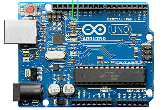
}The Blink Sketch
The "Hello World" of microcontrollers — blink the onboard LED on pin 13:
- Step 1: Set pin 13 as output in
setup() - Step 2: In
loop(), turn LED on → wait → turn LED off → wait delay(ms)pauses execution for the given milliseconds
⚠ Warning: delay() blocks all code execution — nothing else can run during the wait!
Reading a Button
- Use
INPUT_PULLUPto enable the internal pull-up resistor - Button connects pin to GND when pressed
- Logic is inverted: pressed =
LOW, released =HIGH
Why pull-up? Without it, the pin "floats" and reads random values. The pull-up ensures a defined HIGH state when the button is not pressed.
const int BTN = 2;
const int LED = 13;

void setup() {
  pinMode(BTN, INPUT_PULLUP);
  pinMode(LED, OUTPUT);
  Serial.begin(9600);
}

void loop() {
  if (digitalRead(BTN) == LOW) {
    // Button is pressed
    digitalWrite(LED, HIGH);
    Serial.println("Pressed!");
  } else {
    digitalWrite(LED, LOW);
  }
  delay(50);  // Simple debounce
}
Analog to Digital Conversion
Bridging the analog world with digital logic
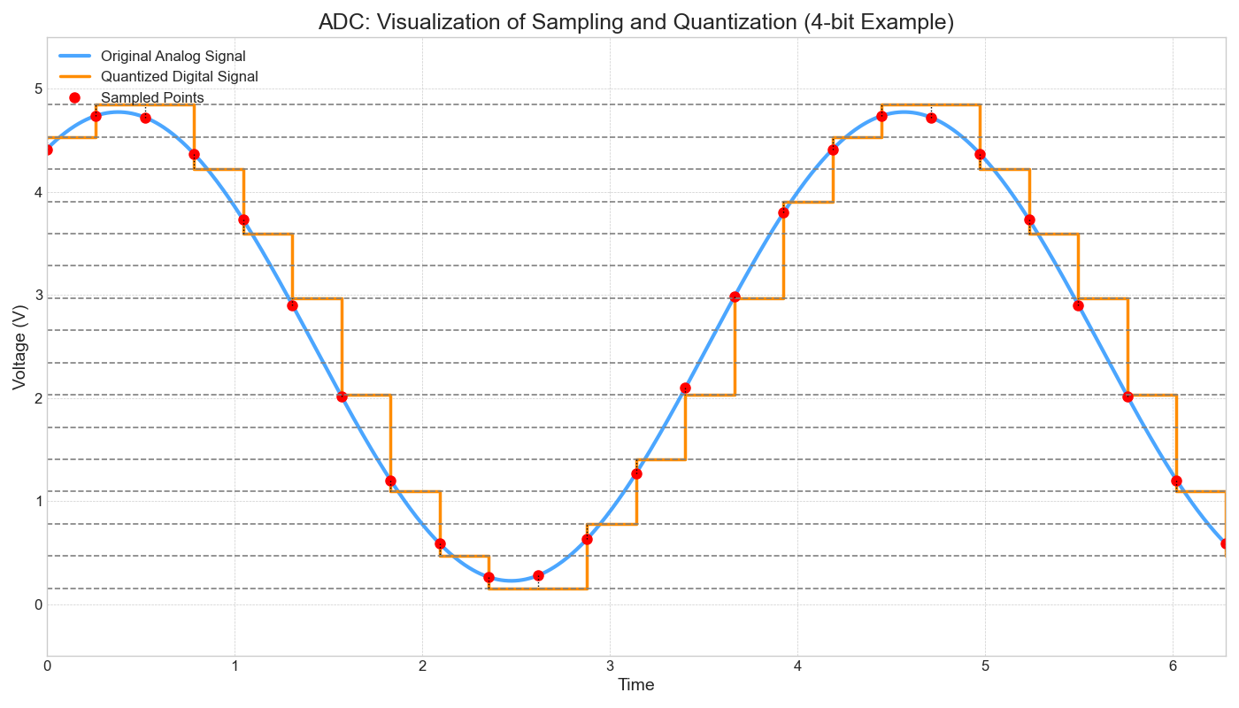
ADC Fundamentals
Real-world signals (temperature, light, sound) are analog — continuous values. The ADC converts them to digital numbers the MCU can process.
Key Concepts:
- Sampling: measuring the signal at regular intervals
- Quantization: mapping each sample to a discrete level
- Resolution: number of bits → number of levels
Arduino Uno ADC:
10-bit resolution → 210 = 1024 levels (0–1023)
Formula: Digital = (Vin / Vref) × 1023
analogRead() in Action
Reading analog sensors is straightforward:
analogRead(pin)returns a value from 0 to 1023- Common sensors: potentiometer, LDR, thermistor, joystick
- Use
map()to scale values to a useful range
Example: A potentiometer at half-turn with 5V reference reads ~512.
const int POT_PIN = A0;

void setup() {
  Serial.begin(9600);
}

void loop() {
  int raw = analogRead(POT_PIN);

  // Convert to voltage
  float voltage = raw * (5.0 / 1023.0);

  // Map to percentage (0-100)
  int percent = map(raw, 0, 1023, 0, 100);

  Serial.print("Raw: ");
  Serial.print(raw);
  Serial.print(" | Voltage: ");
  Serial.print(voltage, 2);
  Serial.print("V | ");
  Serial.print(percent);
  Serial.println("%");

  delay(200);
}
Serial Plotter
The Arduino IDE includes a Serial Plotter — a real-time graph of serial data.
- Open via Tools → Serial Plotter
- Each
Serial.println()value is plotted as a point - Multiple values per line (tab or space separated) plot as multiple lines
Great for: Visualizing sensor data, debugging analog readings, tuning thresholds.
// Plot two sensors on the same graph
void setup() {
  Serial.begin(9600);
}

void loop() {
  int sensor1 = analogRead(A0);
  int sensor2 = analogRead(A1);

  // Tab-separated for multi-line plot
  Serial.print(sensor1);
  Serial.print("\t");
  Serial.println(sensor2);

  delay(50);
}
Timing & State Machines
Writing responsive, non-blocking code
The Problem with delay()
delay() is a blocking function — nothing else happens during the wait:
- Can't read buttons while delay is running
- Can't update displays or check sensors
- Can't run two tasks at different speeds
Try this mentally: Blink an LED every 1 second AND read a button. With delay(1000), the button check only runs once per second!
// ❌ BAD — blocking approach
void loop() {
  // Blink LED
  digitalWrite(13, HIGH);
  delay(1000);            // ← STUCK HERE for 1 sec
  digitalWrite(13, LOW);
  delay(1000);            // ← STUCK HERE for 1 sec

  // This button check barely runs!
  if (digitalRead(2) == LOW) {
    Serial.println("Pressed");
  }
}
// Total loop time: ~2 seconds
// Button is only checked once every 2 sec!
Non-blocking with millis()
millis() returns the number of milliseconds since the Arduino started.
The Pattern:
- Store the time of last action in
previousMillis - On each
loop(), check: has enough time passed? - If yes → do the action and update
previousMillis
The loop keeps running at full speed — other code can execute between checks!
// ✅ GOOD — non-blocking approach
unsigned long previousMillis = 0;
const long interval = 1000;
bool ledState = false;

void loop() {
  unsigned long currentMillis = millis();

  if (currentMillis - previousMillis >= interval) {
    previousMillis = currentMillis;
    ledState = !ledState;
    digitalWrite(13, ledState);
  }

  // This runs EVERY loop iteration!
  if (digitalRead(2) == LOW) {
    Serial.println("Pressed");
  }
}
// Loop runs thousands of times per second
Multitasking with millis()
Run multiple timed tasks independently:
- Each task has its own
previousMillisandinterval - Tasks don't block each other
- Use separate functions for each task (modular design)
- The
statickeyword preserves a variable's value between function calls
void blinkTask() {
static unsigned long prevMs = 0;
static bool state = false;
if (millis() - prevMs >= 500) {
prevMs = millis();
state = !state;
digitalWrite(13, state);
}
}
void sensorTask() {
static unsigned long prevMs = 0;
if (millis() - prevMs >= 2000) {
prevMs = millis();
int val = analogRead(A0);
Serial.println(val);
}
}
void loop() {
blinkTask(); // Runs every 500ms
sensorTask(); // Runs every 2000ms
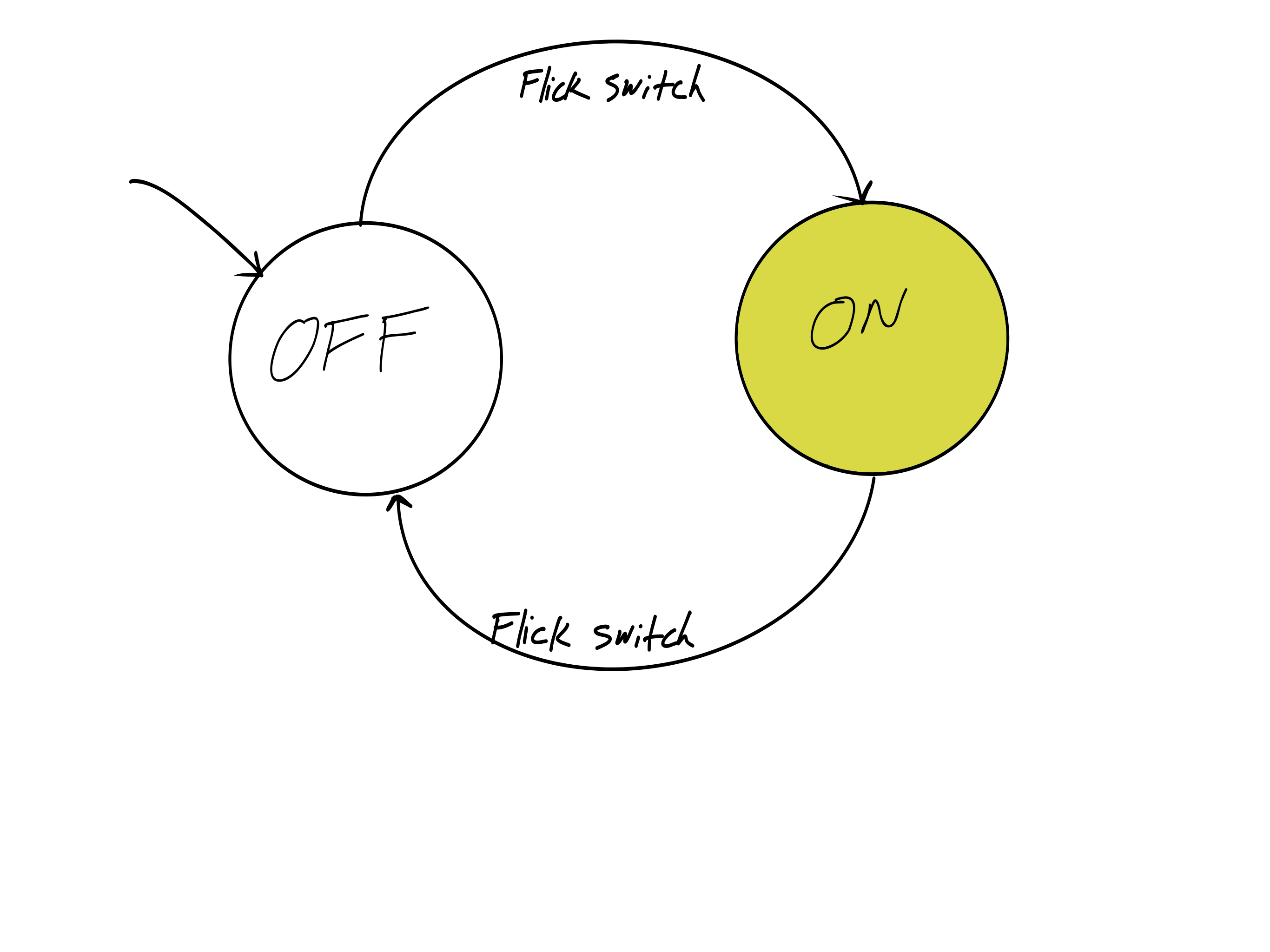
}Finite State Machines (FSM)
An FSM is a model where a system can be in exactly one state at a time, and transitions between states based on events.
Components:
- States — distinct modes of operation (e.g., IDLE, ACTIVE, ALARM)
- Transitions — conditions that cause state changes
- Events — inputs that trigger transitions (button press, timer, sensor)
Real-world: Traffic lights, vending machines, elevators, game AI
FSM Implementation in C++
Use enum class for states and a switch statement in loop():
enum class— gives type-safe, named constants for each stateswitch— selects the behavior for the current state- Each case handles its logic and checks for transitions
enum class State {
  IDLE,
  ACTIVE,
  ALARM
};

State currentState = State::IDLE;

void loop() {
  switch (currentState) {
    case State::IDLE:
      // Do idle things...
      if (digitalRead(BTN) == LOW) {
        currentState = State::ACTIVE;
      }
      break;

    case State::ACTIVE:
      // Do active things...
      if (analogRead(A0) > 900) {
        currentState = State::ALARM;
      }
      break;

    case State::ALARM:
      // Sound alarm...
      if (digitalRead(RESET_BTN) == LOW) {
        currentState = State::IDLE;
      }
      break;
  }
}
FSM Example: Traffic Light
A traffic light with three states and timed transitions:
- GREEN → 5 seconds → YELLOW
- YELLOW → 2 seconds → RED
- RED → 5 seconds → GREEN
Uses the millis() pattern for non-blocking timing within each state.
enum class Light { GREEN, YELLOW, RED };
Light state = Light::GREEN;
unsigned long stateStart = 0;

void loop() {
  unsigned long elapsed = millis() - stateStart;

  switch (state) {
    case Light::GREEN:
      setLights(HIGH, LOW, LOW);
      if (elapsed >= 5000) {
        state = Light::YELLOW;
        stateStart = millis();
      }
      break;

    case Light::YELLOW:
      setLights(LOW, HIGH, LOW);
      if (elapsed >= 2000) {
        state = Light::RED;
        stateStart = millis();
      }
      break;

    case Light::RED:
      setLights(LOW, LOW, HIGH);
      if (elapsed >= 5000) {
        state = Light::GREEN;
        stateStart = millis();
      }
      break;
  }
}
What's Coming in Microcontrollers 2
Building on everything you've learned, we'll dive deeper into the ATmega328P:
🔧 Core Topics
- Timers & Counters — hardware timing, PWM generation
- Timer Interrupts — precise, automatic function calls
- Pin Change Interrupts (PCINT) — react to pin changes instantly
- Advanced Debugging with PlatformIO
🌐 Advanced Topics
- IoT with Arduino — ESP8266, AT commands, WiFi
- Arduino Unplugged — standalone ATmega328P without the board
- ISP Programming, fuses, and bootloaders
- 3 Labs + 2 Assignments + Class Test
Questions?
Next session: Timers, Counters & PWM
📋 Don't forget to check the course schedule for upcoming deliverables
Practice session slides available separately