Understanding Interrupts on the ATmega328P
DE6417 Microcontrollers 2 — Week 2, Session 1
From polling to event-driven firmware
Learning Objectives
- Understand what an interrupt is and why it matters in firmware
- Compare polling vs. interrupt-driven approaches
- Describe how an interrupt works at the CPU level (save state → ISR → restore)
- Read the ATmega328P interrupt vector table
- Identify External Interrupts (INT0 / INT1) and their trigger modes
- Identify Pin Change Interrupts (PCINT0–2) and their limitations
- Understand the role of
volatilein interrupt-safe code - Build a polling-based button-toggle demo (foundation for next session's ISR version)
Part 1: What is an Interrupt?
The event-driven paradigm for embedded systems
The Interrupt Concept
An interrupt is an event (external or internal) that:
- Halts the current thread of execution
- Saves the processor state (PC, status register)
- Jumps to an Interrupt Service Routine (ISR)
- Executes the ISR code
- Restores the saved state
- Resumes exactly where it left off
Who Needs Interrupts?
Your background determines your familiarity:
- High-level / Web programmers: Likely never used interrupts directly — event listeners and callbacks abstract them away
- PC-level C/C++ programmers: May know the concept — OS APIs expose interrupts as callback functions (e.g., timer callbacks, signal handlers)
- Firmware / Embedded programmers: Must set up interrupts manually — no OS to do it for you
Polling: The Problem
Polling = the CPU explicitly reads an I/O pin (or register) every loop iteration to check if something happened.
- Every single loop: "Is button pressed? No. Is button pressed? No. Is button pressed? …"
- CPU is busy even when nothing is happening
- Wastes cycles, wastes power, increases latency
Interrupts: The Solution
Instead of checking pins yourself, dedicated hardware inside the microcontroller monitors the pins continuously.
- Hardware watches for a pin change (rising edge, falling edge, level, etc.)
- When the event fires, the CPU is interrupted automatically
- Your ISR runs only when needed — zero CPU cost otherwise
- The CPU is free to do useful work (or sleep!) the rest of the time
Polling vs. Interrupts
| Aspect | Polling | Interrupts |
|---|---|---|
| CPU Usage | Continuously busy checking | Only active when event fires |
| Response Time | Depends on loop speed | Near-instant (few clock cycles) |
| Power | Higher — CPU always running | Lower — CPU can sleep between events |
| Code Complexity | Simple — just read in a loop | Slightly more setup, but cleaner architecture |
| Scalability | Slows down with more devices | Each device gets its own trigger |
| Best For | Simple, fast-changing signals | Infrequent events, low-power, real-time systems |
How an Interrupt Works (Step-by-Step)
- CPU is executing Instruction N in your main code
- An interrupt event is detected by hardware
- Instruction N finishes (the CPU never stops mid-instruction)
- CPU saves the Program Counter (PC) and Status Register (SREG) onto the stack
- CPU looks up the ISR address from the interrupt vector table
- ISR code executes
- ISR returns with
RETIinstruction - CPU restores PC + SREG from the stack
- Execution continues at Instruction N+1
The Instruction Boundary
The CPU never stops in the middle of an instruction. The current instruction always finishes first.
- Interrupt arrives during Instruction N
- Instruction N completes
- Then the CPU responds to the interrupt
Interrupt Latency on AVR
On the ATmega328P at 16 MHz, this is roughly 4–5 clock cycles ≈ 0.25–0.31 µs
Part 2: ATmega328P Interrupt System
Vectors, sources & configurations
Interrupt Vector Table
The ATmega328P has 26 interrupt vectors stored at the beginning of flash memory. Each is a 2-byte jump address.
| Vec # | Address | Source | Description |
|---|---|---|---|
| 1 | 0x0000 | RESET | External pin, power-on, brown-out, watchdog reset |
| 2 | 0x0002 | INT0 | External Interrupt Request 0 (PD2) |
| 3 | 0x0004 | INT1 | External Interrupt Request 1 (PD3) |
| 4 | 0x0006 | PCINT0 | Pin Change Interrupt Bank 0 (PB0–PB5) |
| 5 | 0x0008 | PCINT1 | Pin Change Interrupt Bank 1 (PC0–PC5) |
| 6 | 0x000A | PCINT2 | Pin Change Interrupt Bank 2 (PD0–PD7) |
| 7 | 0x000C | WDT | Watchdog Timer |
| 8 | 0x000E | TIMER2_COMPA | Timer/Counter2 Compare Match A |
| 9 | 0x0010 | TIMER2_COMPB | Timer/Counter2 Compare Match B |
| 10 | 0x0012 | TIMER2_OVF | Timer/Counter2 Overflow |
| 11 | 0x0014 | TIMER1_CAPT | Timer/Counter1 Input Capture |
| 12 | 0x0016 | TIMER1_COMPA | Timer/Counter1 Compare Match A |
| 13 | 0x0018 | TIMER1_COMPB | Timer/Counter1 Compare Match B |
| 14 | 0x001A | TIMER1_OVF | Timer/Counter1 Overflow |
| 15 | 0x001C | TIMER0_COMPA | Timer/Counter0 Compare Match A |
| 16 | 0x001E | TIMER0_COMPB | Timer/Counter0 Compare Match B |
| 17 | 0x0020 | TIMER0_OVF | Timer/Counter0 Overflow |
| 18 | 0x0022 | SPI_STC | SPI Serial Transfer Complete |
| 19 | 0x0024 | USART_RX | USART Receive Complete |
| 20 | 0x0026 | USART_UDRE | USART Data Register Empty |
| 21 | 0x0028 | USART_TX | USART Transmit Complete |
| 22 | 0x002A | ADC | ADC Conversion Complete |
| 23 | 0x002C | EE_READY | EEPROM Ready |
| 24 | 0x002E | ANALOG_COMP | Analog Comparator |
| 25 | 0x0030 | TWI | Two-Wire Interface (I²C) |
| 26 | 0x0032 | SPM_READY | Store Program Memory Ready |
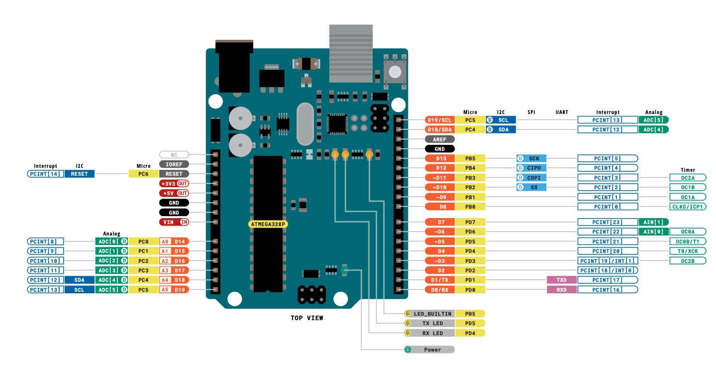
Hover to enlarge pinout
Interrupt Sources — Categories
🔴 External Interrupts
- INT0 — Pin 2 (PD2)
- INT1 — Pin 3 (PD3)
🔵 Pin Change Interrupts
- PCINT0 — Port B (PB0–PB5)
- PCINT1 — Port C (PC0–PC5)
- PCINT2 — Port D (PD0–PD7)
🟢 Timer / Counter
- Timer0/1/2 Overflow
- Timer0/1/2 Compare Match A & B
- Timer1 Input Capture
🟣 Communication
- SPI Transfer Complete
- USART RX / TX / Data Reg Empty
- TWI (I²C)
🟡 Other
- ADC Conversion Complete
- Analog Comparator
- Watchdog Timer
- EEPROM Ready / SPM Ready
External Interrupts: INT0 & INT1
These are the "premium" interrupts on the ATmega328P:
- Each has its own dedicated ISR vector
- Configurable trigger: rising edge, falling edge, low level, or any change
- INT0 lives on Arduino Pin 2 (PD2)
- INT1 lives on Arduino Pin 3 (PD3)
- These pins are fixed — no remapping on the ATmega328P
INT0 / INT1 Trigger Modes
Configured via the EICRA register (External Interrupt Control Register A):
| ISCx1 | ISCx0 | Trigger | Description |
|---|---|---|---|
| 0 | 0 | Low Level | Interrupt fires continuously while pin is LOW |
| 0 | 1 | Any Change | Fires on both rising and falling edges |
| 1 | 0 | Falling Edge ↓ | Fires on HIGH → LOW transition |
| 1 | 1 | Rising Edge ↑ | Fires on LOW → HIGH transition |
x = 0 for INT0, 1 for INT1. The bits are ISC01:ISC00 and ISC11:ISC10.
After configuring EICRA, enable the interrupt in EIMSK (External Interrupt Mask Register) by setting bit INT0 or INT1.
Pin Change Interrupts (PCINT)
Every GPIO pin on the ATmega328P can generate a Pin Change Interrupt, but they are grouped into three banks:
| Bank | ISR Vector | Port | Pins | Arduino Pins |
|---|---|---|---|---|
| PCINT0 | PCINT0_vect | Port B | PB0–PB5 | D8–D13 |
| PCINT1 | PCINT1_vect | Port C | PC0–PC5 | A0–A5 |
| PCINT2 | PCINT2_vect | Port D | PD0–PD7 | D0–D7 |
PCICR, select individual pins via PCMSK0, PCMSK1, PCMSK2.
External vs. Pin Change Interrupts
| Feature | INT0 / INT1 | PCINT0 / PCINT1 / PCINT2 |
|---|---|---|
| Number of pins | 2 (Pin 2 & Pin 3 only) | ~20 (almost every GPIO) |
| Dedicated ISR? | ✅ Yes — one per pin | ❌ No — one per bank (6–8 pins) |
| Edge selection | Rising, Falling, Level, Any | Any change only |
| Pin identification | Automatic | Manual (compare old vs. new state) |
| Setup complexity | Simple | More bookkeeping needed |
| Arduino API support | ✅ attachInterrupt() | ❌ Not in standard API |
Other Important Interrupt Sources
⏱ Timer Interrupts
- Overflow: Timer wraps around (0xFF→0x00 or 0xFFFF→0x0000)
- Compare Match: Timer value matches a preset value (OCRnA/B)
- Input Capture: External event timestamp (Timer1 only)
📡 SPI (Serial Peripheral Interface)
- Transfer Complete — no need to poll if data was sent
📨 USART (Serial)
- RX Complete: A byte arrived
- TX Complete: Byte fully shifted out
- Data Register Empty: Ready for next byte
🔌 TWI (I²C)
- State change on the bus
🐕 Watchdog Timer
- System reset on hang / periodic wake-up from sleep
Arduino Execution Model
Remember how the Arduino framework works under the hood:
- The C runtime calls startup code → sets up the stack, peripherals
- Then it calls a hidden
main()function you don't write - That
main()callssetup()once - Then enters an infinite loop calling
loop()forever
setup() or loop(), an interrupt can fire at any time and temporarily take control.
// Hidden Arduino main() — you don't write this!
int main(void) {
    init();           // Hardware init

    setup();          // Your setup code — runs once

    while (1) {
        loop();       // Your loop code — runs forever
    }

    return 0;         // Never reached
}

// ⚡ Interrupts can fire ANYWHERE
// during setup() or loop() execution!
Part 3: Practical Demo — Polling Approach
Building the foundation before we add interrupts
Hardware Setup
Components needed:
- 2 × Push buttons → connected to Pin 2 and Pin 3
- Buttons pull pins to GND when pressed (using internal pull-ups)
- 2 × LEDs + resistors → connected to Pin 8 and Pin 9
- Bypass capacitors on the power rails
- Optional: 0.1 µF debounce capacitors on button lines
Pin-to-Port Mapping
Every Arduino pin maps to a specific Port Register bit:
| Arduino Pin | Port.Bit | Function | Direction Reg | Data Reg |
|---|---|---|---|---|
| Pin 2 | PD2 | Button 1 / INT0 | DDRD bit 2 | PORTD bit 2 |
| Pin 3 | PD3 | Button 2 / INT1 | DDRD bit 3 | PORTD bit 3 |
| Pin 8 | PB0 | LED 1 output | DDRB bit 0 | PORTB bit 0 |
| Pin 9 | PB1 | LED 2 output | DDRB bit 1 | PORTB bit 1 |
DDRx sets direction (0 = input, 1 = output). PORTx drives output or enables pull-up on inputs. PINx reads the actual pin state.
Code: Includes & Globals
Organise your code with clear sections:
#include <Arduino.h>— needed for standalone compilation#definefor pin numbers — easy to change latervolatilevariables for state that will be shared with ISRs
volatile now? We're preparing for the interrupt version. Making them volatile from the start is good practice.
// ── Includes ──
#include <Arduino.h>

// ── Pin Definitions ──
#define BUTTON1_PIN  2   // INT0 lives here
#define BUTTON2_PIN  3   // INT1 lives here
#define LED1_PIN     8   // Port B, bit 0
#define LED2_PIN     9   // Port B, bit 1

// ── Global State ──
volatile int led1_state = 0;
volatile int led2_state = 0;

// String buffer for serial output
char buf[80];
Understanding volatile
The C/C++ compiler can optimise away variables it thinks never change:
- In your
loop(),led1_statemight never be assigned a new value - The optimizer says: "This variable never changes — I'll just cache it in a register"
- But an ISR does change it — the optimizer doesn't see ISR modifications!
- Result without
volatile: main code never sees updated values → bug!
volatile. This forces the compiler to re-read it from RAM every time.
❌ Without volatile
Compiler caches value in register.
ISR changes RAM → main never sees it.
Bug: LED never toggles!
✅ With volatile
Compiler reads from RAM every time.
ISR changes RAM → main sees it.
Works correctly!
Code: setup()
- Configure buttons as INPUT_PULLUP — internal pull-up to VCC, button press goes LOW
- Configure LEDs as OUTPUT
- Start serial for debugging
void setup() {
  // Buttons: INPUT with internal pull-up
  pinMode(BUTTON1_PIN, INPUT_PULLUP);
  pinMode(BUTTON2_PIN, INPUT_PULLUP);

  // LEDs: OUTPUT
  pinMode(LED1_PIN, OUTPUT);
  pinMode(LED2_PIN, OUTPUT);

  // Serial for debug output
  Serial.begin(9600);
  Serial.println("Polling Demo Ready");
}
Code: Reading & Toggling
The polling approach — read each button every loop iteration:
digitalRead()returnsLOW(0) when pressed- Toggle with
!state(NOT operator) delay(200)for crude debounce
digitalRead() calls happen every single loop iteration — even when no button is pressed.
void loop() {
  static int count = 0;
  int btn1, btn2;

  // ── Poll Button 1 ──
  btn1 = digitalRead(BUTTON1_PIN);
  if (btn1 == LOW) {
    led1_state = !led1_state;  // Toggle
    delay(200);                // Debounce
  }

  // ── Poll Button 2 ──
  btn2 = digitalRead(BUTTON2_PIN);
  if (btn2 == LOW) {
    led2_state = !led2_state;  // Toggle
    delay(200);                // Debounce
  }

  // ── Drive LEDs ──
  digitalWrite(LED1_PIN, led1_state);
  digitalWrite(LED2_PIN, led2_state);

  // ... continues on next slide
}
Code: Serial Monitoring
Print the state to Serial for debugging and visualisation:
sprintf()builds a formatted string- Shows loop count, LED states, and button states
- Small delay so the terminal is readable
On the serial monitor you'll see the counter incrementing and state changes when buttons are pressed.
  // ── Serial Output ──
  sprintf(buf,
    "Count:%d L1:%d L2:%d B1:%d B2:%d\r\n",
    count, led1_state, led2_state,
    btn1, btn2);
  Serial.print(buf);

  count++;
  delay(500);  // Slow down for readability
}
Complete Polling Code
// ════════════════════════════════════════════════
// Polling Demo — LED Toggle with Two Buttons
// No interrupts — everything runs in loop()
// ════════════════════════════════════════════════

#include <Arduino.h>

// ── Pin Definitions ──
#define BUTTON1_PIN  2   // Will become INT0
#define BUTTON2_PIN  3   // Will become INT1
#define LED1_PIN     8   // Port B, bit 0
#define LED2_PIN     9   // Port B, bit 1

// ── Globals (volatile for future ISR use) ──
volatile int led1_state = 0;
volatile int led2_state = 0;
char buf[80];

void setup() {
  pinMode(BUTTON1_PIN, INPUT_PULLUP);
  pinMode(BUTTON2_PIN, INPUT_PULLUP);
  pinMode(LED1_PIN, OUTPUT);
  pinMode(LED2_PIN, OUTPUT);
  Serial.begin(9600);
  Serial.println("Polling Demo Ready");
}

void loop() {
  static int count = 0;
  int btn1, btn2;

  // Poll Button 1
  btn1 = digitalRead(BUTTON1_PIN);
  if (btn1 == LOW) {
    led1_state = !led1_state;
    delay(200);  // Debounce
  }

  // Poll Button 2
  btn2 = digitalRead(BUTTON2_PIN);
  if (btn2 == LOW) {
    led2_state = !led2_state;
    delay(200);  // Debounce
  }

  // Drive LEDs
  digitalWrite(LED1_PIN, led1_state);
  digitalWrite(LED2_PIN, led2_state);

  // Serial monitor output
  sprintf(buf, "Count:%d L1:%d L2:%d B1:%d B2:%d\r\n",
    count, led1_state, led2_state, btn1, btn2);
  Serial.print(buf);

  count++;
  delay(500);
}
Part 4: From Polling to Interrupts — Arduino API
Using attachInterrupt() to replace polling
Recap & Goal
The problem: Every time through loop(), we poll both buttons — even when nothing is pressed. This wastes CPU.
Our goal now: Eliminate polling entirely. Connect GPIO pin-change events to interrupt handlers so the ISR only runs when a button is pressed.
- Step 1: Use the Arduino
attachInterrupt()API (easy way) - Step 2: Configure registers manually (low-level way)
- Compare the generated assembly for both approaches
interrupts() & noInterrupts()
Arduino provides two simple functions to globally enable or disable all interrupts:
| Function | Effect | AVR Instruction |
|---|---|---|
interrupts() | Enable global interrupts | SEI |
noInterrupts() | Disable global interrupts | CLI |
// Arduino API way
noInterrupts();  // Disable all interrupts
// ... critical code ...
interrupts();    // Re-enable interrupts

// Direct AVR way (same effect on ATmega328P)
cli();  // Clear Interrupt flag
sei();  // Set Interrupt flag

// Inline assembly (also valid)
__asm__ __volatile__("cli" ::: "memory");
__asm__ __volatile__("sei" ::: "memory");
SEI & CLI — Assembly Level
These are single-cycle AVR instructions that flip bit 7 of SREG:
Sets the I-bit in SREG to
1. All individually-enabled interrupts can now fire.
Clears the I-bit in SREG to
0. No interrupts will fire (they remain pending).
Hardware independence: Using interrupts() / noInterrupts() is preferred because on non-AVR Arduinos the underlying instruction differs.
attachInterrupt() — Syntax
The Arduino API provides a convenient function to register an interrupt handler:
attachInterrupt(
  digitalPinToInterrupt(pin),  // interrupt number
  ISR,                         // callback function
  mode                          // trigger mode
);
| Parameter | Description |
|---|---|
pin | Digital pin number (2 or 3 on ATmega328P) |
ISR | Function pointer — void myISR(void) |
mode | Trigger condition (see next slide) |
// Example: interrupt on pin 2, falling edge
void button1ISR() {
  led1_state = !led1_state;
}

void setup() {
  pinMode(2, INPUT_PULLUP);
  attachInterrupt(
    digitalPinToInterrupt(2),
    button1ISR,   // function pointer
    FALLING       // trigger mode
  );
}
digitalPinToInterrupt() — Pin Mapping
This helper translates a physical pin number to the correct hardware interrupt number. This keeps your code portable across different boards.
| Board | Usable Interrupt Pins |
|---|---|
| Arduino Uno / Nano / Mini (328P) | Pin 2 (INT0), Pin 3 (INT1) — only 2 pins |
| Arduino Mega 2560 | 2, 3, 18, 19, 20, 21 |
| Arduino Zero / MKR | All digital pins |
| Arduino WiFi Rev2 / Nano Every | All digital pins |
attachInterrupt() on the 328P. Pin Change Interrupts (PCINT) work on every pin — but the API doesn't expose them directly.
Interrupt Trigger Modes
The mode parameter of attachInterrupt() defines when the interrupt fires:
| Constant | Triggers when… | Use case |
|---|---|---|
LOW | Pin is held LOW | Level-sensitive devices |
CHANGE | Pin changes value (either direction) | Detect any state transition |
RISING | Pin goes LOW → HIGH | Button release, signal onset |
FALLING | Pin goes HIGH → LOW | Button press (with pull-up) |
FALLING fires on press (HIGH→LOW). CHANGE fires on both press and release — giving two interrupts per press-release cycle.
ISR Callback — Function Pointer Rules
The second parameter of attachInterrupt() is a function pointer. There are strict rules:
- Return type must be
void - Parameter list must be empty:
void myISR(void) - Pass the function name only — no parentheses
// ✅ Correct — name only (address of function)
attachInterrupt(digitalPinToInterrupt(2), button1ISR, FALLING);

// ❌ Wrong — this CALLS the function immediately!
attachInterrupt(digitalPinToInterrupt(2), button1ISR(), FALLING);
// In C/C++, a function name without ()
// evaluates to the address of that function.
//
// This is called a "function pointer".

void button1ISR() {
  led1_state = !led1_state;
}

// button1ISR  → address 0x05EC (example)
// button1ISR() → calls the function NOW

// attachInterrupt stores that address
// into the vector table machinery so
// the hardware can jump to it on interrupt.
Part 5: Code Walkthrough — attachInterrupt()
Converting our polling demo to use external interrupts
Version 2: Globals & Virtual ISRs
Same pins and globals as the polling version. Two new additions:
- Interrupt counter — tracks how many times ISRs fire (great for debugging)
- Two callback functions — one per button, each toggles its LED and bumps the counter
#define BUTTON1_PIN  2
#define BUTTON2_PIN  3
#define LED1_PIN     8
#define LED2_PIN     9

volatile int led1_state = 0;
volatile int led2_state = 0;
volatile int intCounter = 0;

// ── Virtual ISR for Button 1 ──
void button1ISR() {
  led1_state = !led1_state;
  intCounter++;
}

// ── Virtual ISR for Button 2 ──
void button2ISR() {
  led2_state = !led2_state;
  intCounter++;
}
Version 2: setup() with attachInterrupt()
Pin modes are identical to the polling version. The key change is two attachInterrupt() calls:
- Each call writes to EICRA, EIMSK, and EIFR behind the scenes
- The interrupt is live the instant
attachInterrupt()returns - Any pin change on pin 2 or 3 will immediately invoke the corresponding callback
attachInterrupt() only works on INT0 (pin 2) and INT1 (pin 3) on the ATmega328P.
void setup() {
  Serial.begin(9600);

  // Same pin config as polling version
  pinMode(BUTTON1_PIN, INPUT_PULLUP);
  pinMode(BUTTON2_PIN, INPUT_PULLUP);
  pinMode(LED1_PIN, OUTPUT);
  pinMode(LED2_PIN, OUTPUT);

  // ── Attach interrupts ──
  attachInterrupt(
    digitalPinToInterrupt(BUTTON1_PIN),
    button1ISR,   // function pointer
    FALLING       // trigger on press
  );

  attachInterrupt(
    digitalPinToInterrupt(BUTTON2_PIN),
    button2ISR,
    FALLING
  );
}
Version 2: loop() — No More Polling
The main loop never checks the buttons. All state changes happen in the ISR callbacks.
led1_stateandled2_stateare modified only inside the ISRs- The loop just drives LEDs, prints state, and delays
- Without
volatile, the compiler would optimize these reads away — it sees no loop code changing them
led1_state and led2_state. This is why volatile is essential.
void loop() {
  static int count = 0;

  // Drive LEDs from ISR-updated state
  digitalWrite(LED1_PIN, led1_state);
  digitalWrite(LED2_PIN, led2_state);

  // Print state (button reads are OPTIONAL)
  int btn1 = digitalRead(BUTTON1_PIN);
  int btn2 = digitalRead(BUTTON2_PIN);

  sprintf(buf,
    "Cnt:%d L1:%d L2:%d B1:%d B2:%d Int:%d\r\n",
    count, led1_state, led2_state,
    btn1, btn2, intCounter);
  Serial.print(buf);

  count++;
  delay(500);
}
FALLING vs. CHANGE Mode — Demo
- FALLING: 1 interrupt per press. Counter increments by 1. LED toggles once.
- CHANGE: 2 interrupts per press-release. Counter increments by 2. LED toggles twice (net: no visible change unless you release before the loop updates).
- CHANGE is useful when you need to detect any state transition on a signal — not just a button press.
Complete attachInterrupt() Code
// ════════════════════════════════════════════════
// Version 2 — External Interrupts via attachInterrupt()
// ════════════════════════════════════════════════

#include <Arduino.h>

#define BUTTON1_PIN  2   // INT0
#define BUTTON2_PIN  3   // INT1
#define LED1_PIN     8
#define LED2_PIN     9

volatile int led1_state = 0;
volatile int led2_state = 0;
volatile int intCounter = 0;
char buf[80];

// ── Virtual ISRs ──
void button1ISR() {
  led1_state = !led1_state;
  intCounter++;
}

void button2ISR() {
  led2_state = !led2_state;
  intCounter++;
}

void setup() {
  Serial.begin(9600);
  pinMode(BUTTON1_PIN, INPUT_PULLUP);
  pinMode(BUTTON2_PIN, INPUT_PULLUP);
  pinMode(LED1_PIN, OUTPUT);
  pinMode(LED2_PIN, OUTPUT);

  attachInterrupt(digitalPinToInterrupt(BUTTON1_PIN),
                  button1ISR, FALLING);
  attachInterrupt(digitalPinToInterrupt(BUTTON2_PIN),
                  button2ISR, FALLING);

  Serial.println("attachInterrupt Demo Ready");
}

void loop() {
  static int count = 0;
  digitalWrite(LED1_PIN, led1_state);
  digitalWrite(LED2_PIN, led2_state);

  int btn1 = digitalRead(BUTTON1_PIN);
  int btn2 = digitalRead(BUTTON2_PIN);

  sprintf(buf, "Cnt:%d L1:%d L2:%d B1:%d B2:%d Int:%d\r\n",
    count, led1_state, led2_state, btn1, btn2, intCounter);
  Serial.print(buf);

  count++;
  delay(500);
}
Part 6: Manual Interrupt Setup — Register Level
Going to the metal: ISR macros & direct register writes
The ISR() Macro
To create a real hardware ISR (with RETI), use the ISR() macro:
ISR(vector_name) {
  // your code — keep it SHORT!
}
- The compiler generates proper prologue (push registers) and epilogue (
RETI) - The
vector_namemust match exactly — a wrong name compiles silently but the ISR never fires! - No
attachInterrupt()needed; the macro directly wires the vector table
// ── Real ISR for INT0 ──
ISR(INT0_vect) {
  led1_state = !led1_state;
  intCounter++;
}

// ── Real ISR for INT1 ──
ISR(INT1_vect) {
  led2_state = !led2_state;
  intCounter++;
}

// These are TRUE interrupt service routines:
// - Compiler generates push/pop prologue
// - Ends with RETI (not RET)
// - Hardware disables interrupts on entry
// - RETI re-enables them on exit
Finding Vector Names — iom328p.h
Vector names are defined in the AVR header file for your chip:
avr/include/avr/iom328p.h
| Vector Name | Vector # | Source |
|---|---|---|
INT0_vect | 2 | External Interrupt 0 (Pin 2) |
INT1_vect | 3 | External Interrupt 1 (Pin 3) |
PCINT0_vect | 4 | Pin Change — Port B |
PCINT1_vect | 5 | Pin Change — Port C |
PCINT2_vect | 6 | Pin Change — Port D |
WDT_vect | 7 | Watchdog Timer |
TIMER1_COMPA_vect | 12 | Timer1 Compare Match A |
TIMER0_OVF_vect | 17 | Timer0 Overflow (millis!) |
USART_RX_vect | 19 | USART Receive Complete |
// From iom328p.h:
#define INT0_vect     _VECTOR(1)
#define INT1_vect     _VECTOR(2)
#define PCINT0_vect   _VECTOR(3)
#define PCINT1_vect   _VECTOR(4)
#define PCINT2_vect   _VECTOR(5)
#define WDT_vect      _VECTOR(6)
// ...
#define TIMER1_COMPA_vect _VECTOR(11)
#define TIMER0_OVF_vect   _VECTOR(16)
#define USART_RX_vect     _VECTOR(18)
// ...

// _VECTOR(N) expands to the correct
// label that the linker maps to the
// interrupt vector table entry.
EICRA — External Interrupt Control Register A
Controls the trigger mode (sense control) for INT0 and INT1:
EIMSK — External Interrupt Mask Register
This register enables or disables individual external interrupts:
- Bit 1 (INT1): Set to 1 → enable INT1 interrupt
- Bit 0 (INT0): Set to 1 → enable INT0 interrupt
- Both also require the I-bit in SREG (global interrupt enable) to be set
EIMSK = 0b00000011;
EIFR — External Interrupt Flag Register
This register indicates whether an external interrupt has occurred:
- When an interrupt condition occurs, the corresponding flag is set to
1 - The flag is automatically cleared when the ISR executes
EIFR = 0b00000011; — clears both flags before enabling interrupts.
Version 3: Manual Register Setup
Instead of attachInterrupt(), we configure the three registers directly inside a critical section:
cli()— disable interrupts first- EICRA — set falling edge for both INT0 & INT1
- EIMSK — enable both interrupts
- EIFR — clear any pending flags
sei()— re-enable interrupts
void setup() {
  Serial.begin(9600);
  pinMode(BUTTON1_PIN, INPUT_PULLUP);
  pinMode(BUTTON2_PIN, INPUT_PULLUP);
  pinMode(LED1_PIN, OUTPUT);
  pinMode(LED2_PIN, OUTPUT);

  // ── Critical Section: configure interrupts ──
  cli();  // Disable all interrupts

  // EICRA: falling edge for both
  // ISC11:ISC10 = 10 (INT1 falling)
  // ISC01:ISC00 = 10 (INT0 falling)
  EICRA = 0b00001010;

  // EIMSK: enable INT0 and INT1
  EIMSK = 0b00000011;

  // EIFR: clear any pending flags
  EIFR  = 0b00000011;

  sei();  // Re-enable interrupts
}
Complete Manual Register Code
// ════════════════════════════════════════════════
// Version 3 — Manual Register Configuration
// True ISRs with ISR() macro + direct register writes
// ════════════════════════════════════════════════

#include <Arduino.h>

#define BUTTON1_PIN  2   // INT0 (PD2)
#define BUTTON2_PIN  3   // INT1 (PD3)
#define LED1_PIN     8
#define LED2_PIN     9

volatile int led1_state = 0;
volatile int led2_state = 0;
volatile int intCounter = 0;
char buf[80];

// ── True ISRs (generates RETI) ──
ISR(INT0_vect) {
  led1_state = !led1_state;
  intCounter++;
}

ISR(INT1_vect) {
  led2_state = !led2_state;
  intCounter++;
}

void setup() {
  Serial.begin(9600);
  pinMode(BUTTON1_PIN, INPUT_PULLUP);
  pinMode(BUTTON2_PIN, INPUT_PULLUP);
  pinMode(LED1_PIN, OUTPUT);
  pinMode(LED2_PIN, OUTPUT);

  // ── Critical section: configure interrupt registers ──
  cli();                    // Disable global interrupts

  EICRA = 0b00001010;      // Falling edge on INT0 & INT1
  EIMSK = 0b00000011;      // Enable INT0 & INT1
  EIFR  = 0b00000011;      // Clear pending flags

  sei();                    // Re-enable global interrupts

  Serial.println("Manual Register Interrupt Demo Ready");
}

void loop() {
  static int count = 0;
  digitalWrite(LED1_PIN, led1_state);
  digitalWrite(LED2_PIN, led2_state);

  int btn1 = digitalRead(BUTTON1_PIN);
  int btn2 = digitalRead(BUTTON2_PIN);

  sprintf(buf, "Cnt:%d L1:%d L2:%d B1:%d B2:%d Int:%d\r\n",
    count, led1_state, led2_state, btn1, btn2, intCounter);
  Serial.print(buf);

  count++;
  delay(500);
}
Part 7: ISR Best Practices & Critical Sections
Rules, pitfalls, and protecting shared data
ISR Rules of Thumb
Tens to hundreds of instructions at most. Get in, do the work, get out.
Serial.print(), printf(), sprintf(), delay() — all dangerous inside an ISR.delay() relies on Timer0 interrupts, which are disabled while you're in an ISR!
volatile for shared variablesAny variable modified in an ISR and read in
loop() must be volatile.
Timer0 drives
millis(), micros(), and delay(). The Serial system also uses interrupts. If you stay in an ISR too long, you can corrupt serial data or lose timing accuracy.
Nested Interrupts & RETI Behaviour
On the ATmega328P, when an ISR begins:
- Hardware clears the I-flag (global interrupt disable)
- Program counter is pushed onto the stack
- CPU jumps to the vector table entry
- Your ISR code executes — no other interrupts can fire
RETIpops the PC and sets the I-flag back to 1
sei() inside your ISR. But beware: if the same interrupt re-fires, you get recursion on the stack. Only do this if you know exactly what you're doing.
Critical Sections — Protecting Shared Data
A critical section is a region of code where interrupts are disabled to prevent data corruption:
- Use when main code and ISR share multi-byte variables
- Without protection, an ISR can fire mid-update and see half-written data
- Keep critical sections as short as possible
// ── Example: protecting a shared variable ──
volatile long sharedData = 0;

// In loop():
void loop() {
  long localCopy;

  // ── Critical section ──
  noInterrupts();          // cli()
  localCopy = sharedData;  // Atomic read
  interrupts();            // sei()

  // Now use localCopy safely — ISR can't
  // interrupt the 4-byte read above
  Serial.println(localCopy);
}

// In ISR:
ISR(INT0_vect) {
  sharedData++;  // ISR modifies the shared data
}
Atomic Operations & Data Integrity
An atomic operation is one that cannot be interrupted mid-execution:
| Operation | Atomic on 8-bit AVR? | Why? |
|---|---|---|
Read/write uint8_t | ✅ Yes | Single byte = single instruction |
Read/write int (16-bit) | ❌ No | Requires two instructions (low + high byte) |
Read/write long (32-bit) | ❌ No | Four instructions |
Read-modify-write (e.g., x++) | ❌ No | Load + modify + store = 3+ instructions |
cli() … sei()
Interrupt Queuing on ATmega328P
On the ATmega328P, there is no interrupt queue. Each interrupt source has a single flag bit:
Quiz: attachInterrupt()
Q5: What does attachInterrupt(digitalPinToInterrupt(2), myISR, FALLING) do?
Quiz: Register Configuration
Q6: To set INT0 for falling-edge detection, which value goes into the lower 2 bits of EICRA (ISC01:ISC00)?
Quiz: Critical Sections
Q7: Why should you use cli() / sei() when reading a volatile long variable that is modified by an ISR?
Summary — Interrupts on the ATmega328P
| Topic | Key Takeaway |
|---|---|
| Polling vs Interrupts | Interrupts free the CPU from constant checking |
attachInterrupt() | Easy API — works on pin 2 & 3 (INT0/INT1) on 328P |
| Trigger Modes | LOW, CHANGE, RISING, FALLING |
| Manual Registers | EICRA (mode), EIMSK (enable), EIFR (flags) |
ISR() macro | Creates real ISRs with RETI — vector names from headers |
volatile | Required for any variable shared between ISR and main |
| Critical Sections | cli()/sei() to protect multi-byte shared data |
| Virtual vs Real ISR | attachInterrupt = RET (callback); ISR() = RETI (true ISR) |
| No queuing | ATmega328P can lose interrupts during long critical sections |
🛠️ Practice Exercise
Button-Press Counter with LED Blink-Rate Stages
Practice Task — Press Counter & LED Blink Rates
loop().
Behaviour
| Press Count | LED State | Blink Delay (ms) |
|---|---|---|
| 0 (start) | OFF (steady) | 0 — LED stays OFF |
| 1 | SLOW blink | 1000 |
| 2 | MEDIUM blink | 500 |
| 3 | FAST blink | 100 |
| 4 | OFF (cycle restarts) | 0 |
Hardware
- 1 × Push button → Pin 2 (INT0), wired to GND, internal pull-up
- 1 × LED + 220 Ω resistor → Pin 8, wired to GND
Two Versions Required
| Version A — Arduino API | Version B — Manual Registers |
|---|---|
attachInterrupt() |
ISR() macro + EICRA / EIMSK |
Version A — Arduino API Skeleton
// ════════════════════════════════════════════════
// Practice Version A — Using attachInterrupt()
// Button-press counter with 4 LED blink-rate stages
// ════════════════════════════════════════════════

#include <Arduino.h>

#define BUTTON_PIN  2   // INT0 (PD2)
#define LED_PIN     8

// Blink delay lookup (ms): OFF, SLOW, MEDIUM, FAST
const unsigned int blinkDelay[] = {0, 1000, 500, 100};

// TODO 1: Declare a volatile variable to track
//         which stage we're on (0-3)
// ___________________________________________

// TODO 2: Declare a volatile total press counter
// ___________________________________________

// TODO 3: Write the ISR callback
//         - Advance the stage (wrap around using modulo 4)
//         - Increment the press counter
void buttonISR() {
  // ___________________________________________
  // ___________________________________________
}

void setup() {
  Serial.begin(9600);

  // TODO 4: Set pin modes
  //   - BUTTON_PIN as INPUT_PULLUP
  //   - LED_PIN as OUTPUT
  // ___________________________________________
  // ___________________________________________

  // TODO 5: Attach the interrupt
  //   - Use digitalPinToInterrupt()
  //   - Start with FALLING trigger
  //   - Point to buttonISR
  // ___________________________________________

  Serial.println("Version A — Blink Rate Ready");
}

void loop() {
  unsigned int d = blinkDelay[stage];

  if (d == 0) {
    // TODO 6: Stage 0 — LED should be OFF
    // ___________________________________________
  } else {
    // TODO 7: Blink the LED
    //   - Turn LED ON, delay(d), turn LED OFF, delay(d)
    // ___________________________________________
    // ___________________________________________
    // ___________________________________________
    // ___________________________________________
  }

  // TODO 8: Print stage and press count to Serial
  //   e.g. "Stage: 2 (MED 500ms)  Presses: 7"
  // ___________________________________________
}
Version B — Manual Register Skeleton
// ════════════════════════════════════════════════
// Practice Version B — Manual Registers + ISR()
// No attachInterrupt() allowed!
// ════════════════════════════════════════════════

#include <Arduino.h>

#define BUTTON_PIN  2   // INT0 (PD2)
#define LED_PIN     8

const unsigned int blinkDelay[] = {0, 1000, 500, 100};

// TODO 1: Declare volatile variables
//   - stage (0-3) and press counter
// ___________________________________________
// ___________________________________________

// TODO 2: Write the true ISR using the ISR() macro
//   - Vector name for INT0: ___________
//   - Advance stage (mod 4), increment counter
ISR(/* TODO: vector name */) {
  // ___________________________________________
  // ___________________________________________
}

void setup() {
  Serial.begin(9600);

  // TODO 3: Set pin modes
  // ___________________________________________
  // ___________________________________________

  // TODO 4: Configure registers in a critical section
  cli();

  //   a) EICRA — Set INT0 to FALLING edge
  //      Hint: ISC01=1, ISC00=0 → bits 1:0 = 0b10
  // ___________________________________________

  //   b) EIMSK — Enable INT0
  // ___________________________________________

  //   c) EIFR — Clear any pending flag
  // ___________________________________________

  sei();

  Serial.println("Version B — Blink Rate Ready");
}

void loop() {
  unsigned int d = blinkDelay[stage];

  // TODO 5: Blink logic (same as Version A)
  //   - If d == 0: LED OFF
  //   - Else: ON → delay(d) → OFF → delay(d)
  // ___________________________________________
  // ___________________________________________
  // ___________________________________________
  // ___________________________________________
  // ___________________________________________

  // TODO 6: Serial print stage + count
  // ___________________________________________
}
Part 2 — Trigger Mode Experiment
FALLING, change the trigger mode and observe what happens. Fill in the table below.
| Mode | EICRA Bits (ISC01:ISC00) | When does it fire? | What do you observe? |
|---|---|---|---|
| LOW | 00 |
While pin is held LOW | Write your observation… |
| CHANGE | 01 |
Any logic change (HIGH↔LOW) | Write your observation… |
| FALLING | 10 |
HIGH → LOW transition | Write your observation… |
| RISING | 11 |
LOW → HIGH transition | Write your observation… |
- With LOW mode — does the counter go up by 1, or does it keep firing while the button is held? Why?
- With CHANGE mode — how many times does the ISR fire per press-and-release? Why does that matter for the brightness cycle?
- With RISING mode — does it trigger on press or release? Why?
- Which mode gives the most predictable, single-fire behaviour for a button press?
How to Switch Trigger Modes
Version A — Arduino API
Simply change the third argument of attachInterrupt():
// Try each one and observe the LED behaviour:
attachInterrupt(digitalPinToInterrupt(2), buttonISR, FALLING); // default
attachInterrupt(digitalPinToInterrupt(2), buttonISR, RISING);
attachInterrupt(digitalPinToInterrupt(2), buttonISR, CHANGE);
attachInterrupt(digitalPinToInterrupt(2), buttonISR, LOW);
Version B — Manual Registers
Change bits [1:0] of EICRA (ISC01 and ISC00):
// LOW:     ISC01=0, ISC00=0
EICRA &= ~((1 << ISC01) | (1 << ISC00));   // 0b00

// CHANGE:  ISC01=0, ISC00=1
EICRA = (EICRA & ~(1 << ISC01)) | (1 << ISC00);  // 0b01

// FALLING: ISC01=1, ISC00=0
EICRA = (EICRA | (1 << ISC01)) & ~(1 << ISC00);  // 0b10

// RISING:  ISC01=1, ISC00=1
EICRA |= (1 << ISC01) | (1 << ISC00); // 0b11FALLING is the most reliable choice for a button press with an internal pull-up.
Hints & Checklist
- Use
volatilefor any variable shared between ISR andloop() - Keep ISRs short — only update the stage variable and counter, no Serial calls
- The blink logic uses
delay()inloop()— that's fine, it's not inside the ISR - Use modulo:
stage = (stage + 1) % 4;to cycle through blink rates - For Version B, the INT0 vector name is
INT0_vect
✅ Self-Check
| Check | Version A | Version B |
|---|---|---|
| LED cycles through 4 blink-rate stages? | ☐ | ☐ |
| Serial shows stage name & press count? | ☐ | ☐ |
volatile used for shared vars? | ☐ | ☐ |
| No blocking code inside the ISR? | ☐ | ☐ |
| Tested all 4 trigger modes? | ☐ | ☐ |
| Written explanation of each mode's behaviour? | ☐ | ☐ |
What's Next?
- Timer0, Timer1, Timer2 — architecture & registers
- Prescalers and counter overflow
- Compare Match interrupts for periodic events
- Connecting timers to ISRs for precise timing
- How
millis()anddelay()work internally
See you in the next lecture! 🎯