Pin Change Interrupts (PCINT)
DE6417 Microcontrollers 2
Using Timer and Interrupt Arduino APIs
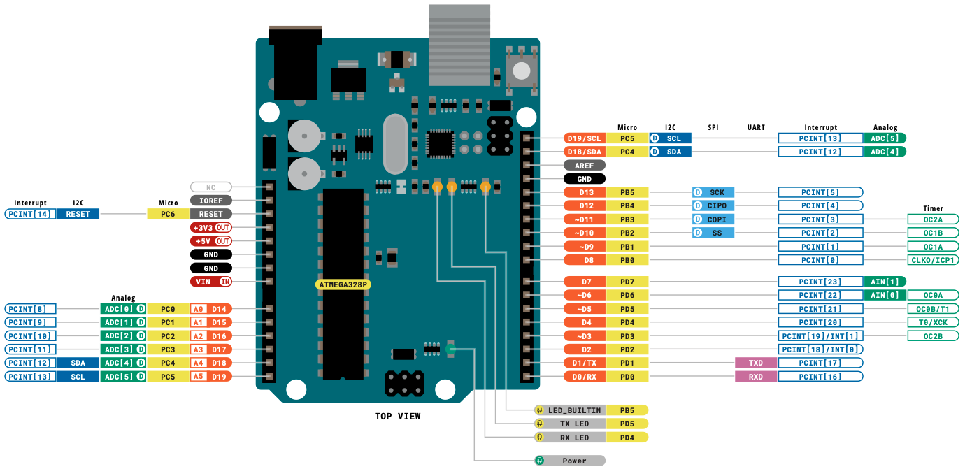
ATmega328P / Arduino Uno
What Are Interrupts?
- Interrupts allow the microcontroller to respond immediately to events
- When an interrupt occurs, the CPU pauses current execution and jumps to an Interrupt Service Routine (ISR)
- After the ISR completes, normal execution resumes
- External Interrupts (INT0, INT1)
- Timer Interrupts
- Data Transmission Interrupts (UART, SPI, I2C)
- Pin Change Interrupts (PCINT) ← Today's focus!
External Interrupts vs Pin Change Interrupts
| Feature | External Interrupts (INT0/INT1) | Pin Change Interrupts (PCINT) |
|---|---|---|
| Available Pins | Only 2 pins (D2, D3) | Almost every GPIO pin (~23 pins) |
| Edge Detection | Rising, Falling, Both, or Level | Any change (both edges only) |
| ISR Vectors | One per pin (INT0_vect, INT1_vect) | One per port group (3 total) |
| Noise Filtering | Built-in hardware filtering | No hardware filtering |
| Complexity | Simpler to configure | Must track pin states manually |
PCINT Pin Groups
Pin Change Interrupts are organized into 3 groups, one for each port:
PCINT 0-7 →
PCINT0_vectArduino: D8-D13
PCINT 8-14 →
PCINT1_vectArduino: A0-A5 (Analog pins)
PCINT 16-23 →
PCINT2_vectArduino: D0-D7
ATmega328P Datasheet — Pin Configurations
328P
Critical Concept: Shared ISR Vectors
- All pins in a group share the same ISR vector
- If multiple pins are enabled, you won't know which one triggered the interrupt
- You must track pin states before and after to determine which changed
(Single ISR)
PCINT Configuration Registers
Only 3 registers needed to configure Pin Change Interrupts:
| Register | Name | Purpose |
|---|---|---|
PCICR |
Pin Change Interrupt Control Register | Enable/disable interrupt groups (ports) |
PCIFR |
Pin Change Interrupt Flag Register | Indicates which group triggered (auto-cleared) |
PCMSK0/1/2 |
Pin Change Mask Registers | Enable specific pins within each group |
PCICR - Pin Change Interrupt Control Register
Click on bits to toggle and see the effect:
0x00 = 0b00000000
PCMSKx - Pin Change Mask Registers
Each group has its own mask register to enable specific pins:
// Enable PCINT8 only (Pin A0)
// PCINT8 is bit 0 of PCMSK1
PCMSK1 = 0b00000001;

// Enable PCINT8 and PCINT9
// (Pins A0 and A1)
PCMSK1 = 0b00000011;

// Enable PCINT0 (Pin D8)
PCMSK0 = 0b00000001;

// Enable PCINT16-23 (all of Port D)
PCMSK2 = 0b11111111;
Interrupt Execution Flow
1 to the bit.
ISR Vector Names
Use these exact names in your ISR() macro:
| Vector Name | Port | PCINT Pins |
|---|---|---|
PCINT0_vect |
Port B | PCINT 0-7 |
PCINT1_vect |
Port C | PCINT 8-14 |
PCINT2_vect |
Port D | PCINT 16-23 |
PCINT1_vect (the ISR for Port C group) with PCINT1 (pin 1 on Port B)!
// ISR for Port B pins (PCINT 0-7)
ISR(PCINT0_vect) {
    // Handle pins D8-D13
}

// ISR for Port C pins (PCINT 8-14)
ISR(PCINT1_vect) {
    // Handle pins A0-A5
}

// ISR for Port D pins (PCINT 16-23)
ISR(PCINT2_vect) {
    // Handle pins D0-D7
}

// Vector names defined in:
// avr/iom328p.h
Basic PCINT Setup
Complete example using PCINT8 (Arduino pin A0):
- Define pins and volatile variables
- Disable interrupts during setup (
cli()) - Enable the interrupt group in PCICR
- Clear any pending flags
- Set the pin mask in PCMSK1
- Re-enable interrupts (
sei())
volatile for variables shared between ISR and main code!
#define LED_PIN 8
#define BUTTON_PIN 14  // A0 = PCINT8

volatile int led_state = 0;
volatile int pcint1_counter = 0;

ISR(PCINT1_vect) {
    led_state ^= 1;      // Toggle LED state
    pcint1_counter++;    // Count interrupts
}

void setup() {
    Serial.begin(9600);
    pinMode(LED_PIN, OUTPUT);
    pinMode(BUTTON_PIN, INPUT_PULLUP);

    cli();  // Disable global interrupts

    // Enable PCINT1 group (Port C)
    PCICR |= 0b00000010;  // Set PCIE1 bit

    // Clear pending interrupt flags
    PCIFR = 0b00000111;

    // Enable only PCINT8 (bit 0)
    PCMSK1 = 0b00000001;

    sei();  // Enable global interrupts
}
Main Loop & Debugging
Tips for the main loop:
- Use
staticvariables to maintain state across loop iterations - Print interrupt counter to debug if interrupts are firing
- Update outputs based on volatile variables set in ISR
void loop() {
    static int loop_counter = 0;
    char buffer[64];

    // Update LED based on ISR state
    digitalWrite(LED_PIN, led_state);

    // Print debug info
    sprintf(buffer,
        "Loop: %d, PCINT: %d, LED: %d",
        loop_counter++,
        pcint1_counter,
        led_state);
    Serial.println(buffer);

    delay(100);
}

// Output example:
// Loop: 0, PCINT: 0, LED: 0
// Loop: 1, PCINT: 0, LED: 0
// [Button pressed]
// Loop: 2, PCINT: 1, LED: 1
// [Button released]
// Loop: 3, PCINT: 2, LED: 0
The "Both Edges" Challenge
Pin Change Interrupts trigger on BOTH rising AND falling edges!
Button Press/Release = 2 Interrupts!
Filtering for One Edge
Solution: Check the pin state inside the ISR!
- Read the current pin value when ISR is called
- If it's HIGH → was a LOW-to-HIGH transition (release)
- If it's LOW → was a HIGH-to-LOW transition (press)
- Only execute your code for the desired edge
ISR(PCINT1_vect) {
    // Check current pin state
    // With INPUT_PULLUP:
    //   HIGH = button released (ignore)
    //   LOW  = button pressed (act on this)

    if (digitalRead(BUTTON_PIN)) {
        // Pin is HIGH → low-to-high transition
        // This was button RELEASE - ignore it
        return;
    }

    // Pin is LOW → high-to-low transition
    // This is button PRESS - do our work
    led_state ^= 1;
    pcint1_counter++;
}

// Alternative: only act on rising edge
ISR(PCINT1_vect) {
    if (!digitalRead(BUTTON_PIN)) {
        return;  // Ignore falling edge
    }
    // Handle rising edge
    doSomething();
}
Detecting Which Pin Changed
When multiple pins are enabled in the same group:
- Store the previous state of all pins
- Read the current state when ISR fires
- XOR them to find which bit(s) changed
- Update stored state for next comparison
changed = previous ^ currentBits that are
1 in changed are the pins that triggered the interrupt.
volatile uint8_t portC_prev = 0xFF;

ISR(PCINT1_vect) {
    // Read current state of Port C
    uint8_t current = PINC;

    // Find which pins changed
    uint8_t changed = portC_prev ^ current;

    // Check each enabled pin
    if (changed & (1 << 0)) {  // PCINT8
        // Pin A0 changed!
        if (!(current & (1 << 0))) {
            // Falling edge on A0
            handleButton1();
        }
    }

    if (changed & (1 << 1)) {  // PCINT9
        // Pin A1 changed!
        if (!(current & (1 << 1))) {
            // Falling edge on A1
            handleButton2();
        }
    }

    // Save for next time
    portC_prev = current;
}
Debouncing Mechanical Switches
Mechanical buttons produce electrical noise (bounce) when pressed:
Solutions:
- Hardware: Add a 0.1μF capacitor between pin and ground
- Software: Ignore interrupts for a short time after first detection
// Software Debounce
volatile unsigned long last_interrupt = 0;
#define DEBOUNCE_MS 50

ISR(PCINT1_vect) {
    unsigned long now = millis();

    // Ignore if too soon after last interrupt
    if (now - last_interrupt < DEBOUNCE_MS) {
        return;
    }
    last_interrupt = now;

    // Only respond to press (falling edge)
    if (digitalRead(BUTTON_PIN)) {
        return;
    }

    // Debounced button press!
    led_state ^= 1;
    pcint1_counter++;
}Add 0.1μF between button pin and GND
Direct Port Access: Why & How
Arduino functions like digitalWrite() are convenient but slow (~50 CPU cycles). Direct port register access takes only ~2 cycles — 25× faster!
Three Registers per Port
| Register | Purpose | Example |
|---|---|---|
DDRx |
Data Direction — set pin as input (0) or output (1) | DDRB |= (1<<PB0); |
PORTx |
Output value — write HIGH (1) or LOW (0) | PORTB |= (1<<PB0); |
PINx |
Input value — read the current pin state | if (PINC & (1<<PC0)) |
Common Bit Operations
| Operation | Arduino Way | Direct Port Way |
|---|---|---|
| Set pin HIGH | digitalWrite(8, HIGH); |
PORTB |= (1<<PB0); |
| Set pin LOW | digitalWrite(8, LOW); |
PORTB &= ~(1<<PB0); |
| Toggle pin | digitalWrite(8, !digitalRead(8)); |
PORTB ^= (1<<PB0); |
| Read pin | digitalRead(A0); |
PINC & (1<<PC0); |
| Set as output | pinMode(8, OUTPUT); |
DDRB |= (1<<PB0); |
digitalWrite() inside ISRs.
328P
Direct Port Access in Practice
Applying DDRx, PORTx & PINx registers to rewrite our PCINT example with direct port access:
Setup — What each line does
DDRB |= (1<<PB0)— set D8 as output (LED)DDRC &= ~(1<<PC0)— set A0 as input (button)PORTC |= (1<<PC0)— enable internal pull-up on A0
ISR — Fast pin operations
PINC & (1<<PC0)— read A0 state directlyPORTB ^= (1<<PB0)— toggle D8 with XOR
Serial.print(), delay(), or any blocking calls inside an ISR. Set a flag and handle it in loop().
// === Full example using direct port access ===

volatile uint8_t led_state = 0;

ISR(PCINT1_vect) {
    // Read A0 (PC0) — only act on falling edge
    if (PINC & (1 << PC0)) return;

    // Toggle LED on D8 (PB0)
    PORTB ^= (1 << PB0);
}

void setup() {
    // Pin direction (DDRx)
    DDRB |= (1 << PB0);    // D8  = output (LED)
    DDRC &= ~(1 << PC0);   // A0  = input  (button)

    // Enable pull-up (PORTx on input pin)
    PORTC |= (1 << PC0);   // Pull-up on A0

    // Interrupt config (same as before)
    cli();
    PCICR  |= (1 << PCIE1);   // Enable group 1
    PCIFR   = 0x07;            // Clear flags
    PCMSK1 |= (1 << PCINT8);  // Enable A0
    sei();
}

void loop() {
    // Main code runs here
}
PCINT Configuration Checklist
Click each step as you complete it:
- Identify which PCINT pin number corresponds to your Arduino pin
- Determine which group (0, 1, or 2) the pin belongs to
- Disable global interrupts with
cli() - Set the correct PCIEx bit in
PCICRto enable the group - Clear any pending flags by writing to
PCIFR - Set the pin's bit in the correct
PCMSKxregister - Re-enable global interrupts with
sei() - Write your ISR with the correct vector name (PCINTx_vect)
- Use
volatilefor all shared variables - Add edge detection and debouncing if needed
Quick Reference Card
| Arduino Pin | PCINT # | Group | Mask Reg |
|---|---|---|---|
| D0 | 16 | 2 | PCMSK2 |
| D1 | 17 | 2 | PCMSK2 |
| D2 | 18 | 2 | PCMSK2 |
| D3 | 19 | 2 | PCMSK2 |
| D8 | 0 | 0 | PCMSK0 |
| D9 | 1 | 0 | PCMSK0 |
| A0 | 8 | 1 | PCMSK1 |
| A1 | 9 | 1 | PCMSK1 |
| A2 | 10 | 1 | PCMSK1 |
// Complete minimal example

volatile bool buttonPressed = false;

ISR(PCINT1_vect) {
    if (!(PINC & (1 << PC0))) { // A0 low?
        buttonPressed = true;
    }
}

void setup() {
    DDRC &= ~(1 << PC0);   // A0 as input
    PORTC |= (1 << PC0);   // Enable pullup

    cli();
    PCICR |= (1 << PCIE1);  // Enable group 1
    PCMSK1 |= (1 << PCINT8); // Enable PCINT8
    sei();
}

void loop() {
    if (buttonPressed) {
        // Handle button press
        buttonPressed = false;
    }
}
Exercise 1: Configure PCINT for Pin D3
You want to trigger an interrupt when a button on Arduino pin D3 changes state. Fill in each answer and press Enter or click Check.
328P
Exercise 2: Measuring Frequency with PCINT
A signal generator outputs a square wave into Arduino pin D5. We'll use a Pin Change Interrupt to measure its frequency.
- Set the signal generator to output a square wave at 200 Hz (amplitude 5V, offset 2.5V).
- Connect the signal generator output to Channel 1 of the oscilloscope — verify the waveform and frequency on screen.
- Using a BNC T-connector or jumper wire, also connect the signal to Arduino pin D5.
- Connect signal generator GND to Arduino GND (common ground is essential!).
- Upload the code, open Serial Monitor, and compare the measured frequency with the oscilloscope reading.
micros() timestamp
Frequency Detection — How It Works
The Strategy
PCINT fires on both edges. We only want the time between two rising edges (= one full period).
micros()if (PIND & (1 << PD5))PIND reads all 8 bits of Port D at once.(1 << PD5) creates a mask: 0b00100000 (only bit 5 is 1).The
& (AND) isolates bit 5 — the result is non-zero (true) if D5 is HIGH (rising edge),
or zero (false) if D5 is LOW (falling edge).So this line means: "only run the code inside if we caught a rising edge."
// Frequency detection on D5 using PCINT

volatile unsigned long lastRise = 0;
volatile unsigned long period = 0;

ISR(PCINT2_vect) {
    unsigned long now = micros();

    // Only measure rising edges
    if (PIND & (1 << PD5)) {
        period = now - lastRise;
        lastRise = now;
    }
}

void setup() {
    Serial.begin(9600);
    DDRD &= ~(1 << PD5);    // D5 = input
    // No pull-up needed (signal generator drives it)

    cli();
    PCICR  |= (1 << PCIE2);
    PCIFR   = 0x07;
    PCMSK2 |= (1 << PCINT21);
    sei();
}

void loop() {
    if (period > 0) {
        unsigned long p;
        cli(); p = period; sei(); // atomic read
        float freq = 1000000.0 / p;
        Serial.print("Freq: ");
        Serial.print(freq);
        Serial.println(" Hz");
    }
    delay(500);
}
Exercise 2: Frequency Detection — Fill In
A signal generator outputs a square wave into Arduino pin D5. Complete the configuration to measure its frequency using PCINT.
• D5 = PD5 = PCINT21
• Group 2 → PCIE2, PCMSK2
• ISR vector: PCINT2_vect
•
micros() returns μs since boot• Filter for rising edge only!
Exercise 3: Reaction Time Game ⏱️
Build a game that measures how fast you can press a button after an LED lights up — all powered by Pin Change Interrupts!
- LED on D13 (built-in)
- Push button on D2 → GND
- Enable internal pull-up on D2
- Open Serial Monitor at 9600 baud
micros() captures the exact moment of the button press inside the ISR, giving precise reaction times that polling in loop() can't match.
Exercise 3: Complete the Code
Fill in the blanks to build the Reaction Time Game. Use what you learned about PCINT registers, ISR, and micros().
// Reaction Time Game — Pin Change Interrupt
// LED on D13, Button on D2 (PCINT18)

volatile bool pressed = false;
volatile unsigned long endTime = 0;
unsigned long startTime = 0;

void setup() {
  Serial.begin(9600);
  pinMode(13, OUTPUT);       // LED
  pinMode(2, INPUT_PULLUP);  // Button

  // Enable PCINT group 2 (Port D)
  PCICR  |= (1 << PCIE2);
  // Enable PCINT18 (pin D2)
  PCMSK2 |= (1 << PCINT18);
  sei();

  Serial.println("=== Reaction Time Game ===");
}

ISR(PCINT2_vect) {
  // Only on falling edge (button press)
  if (!(PIND & (1 << PD2))) {
    endTime = micros();
    pressed = true;
  }
}

void loop() {
  Serial.println("Get ready...");
  delay(2000 + random(3000)); // 2–5 sec

  // Turn LED ON and record start time
  digitalWrite(13, HIGH);
  startTime = micros();
  pressed = false;

  // Wait for button press
  while (!pressed);

  digitalWrite(13, LOW);

  unsigned long reaction =
      (endTime - startTime) / 1000; // ms

  Serial.print("Reaction time: ");
  Serial.print(reaction);
  Serial.println(" ms");

  if (reaction < 250) Serial.println("Excellent!");
  else if (reaction < 400) Serial.println("Good!");
  else Serial.println("Keep practising!");

  Serial.println();
  delay(2000);
}
Summary: Key Takeaways
- Available on almost every GPIO pin
- Simple 2-register configuration
- Good for multiple button inputs
- Triggers on BOTH edges
- Shared ISR per port group
- Must track pin states manually
- Enable group in PCICR
- Set mask in PCMSKx
- Write ISR(PCINTx_vect)
- Use
volatilefor shared vars - Keep ISRs short and fast
- Add debouncing for buttons